Airtable part 6: Incoming air and pressure control
Parts
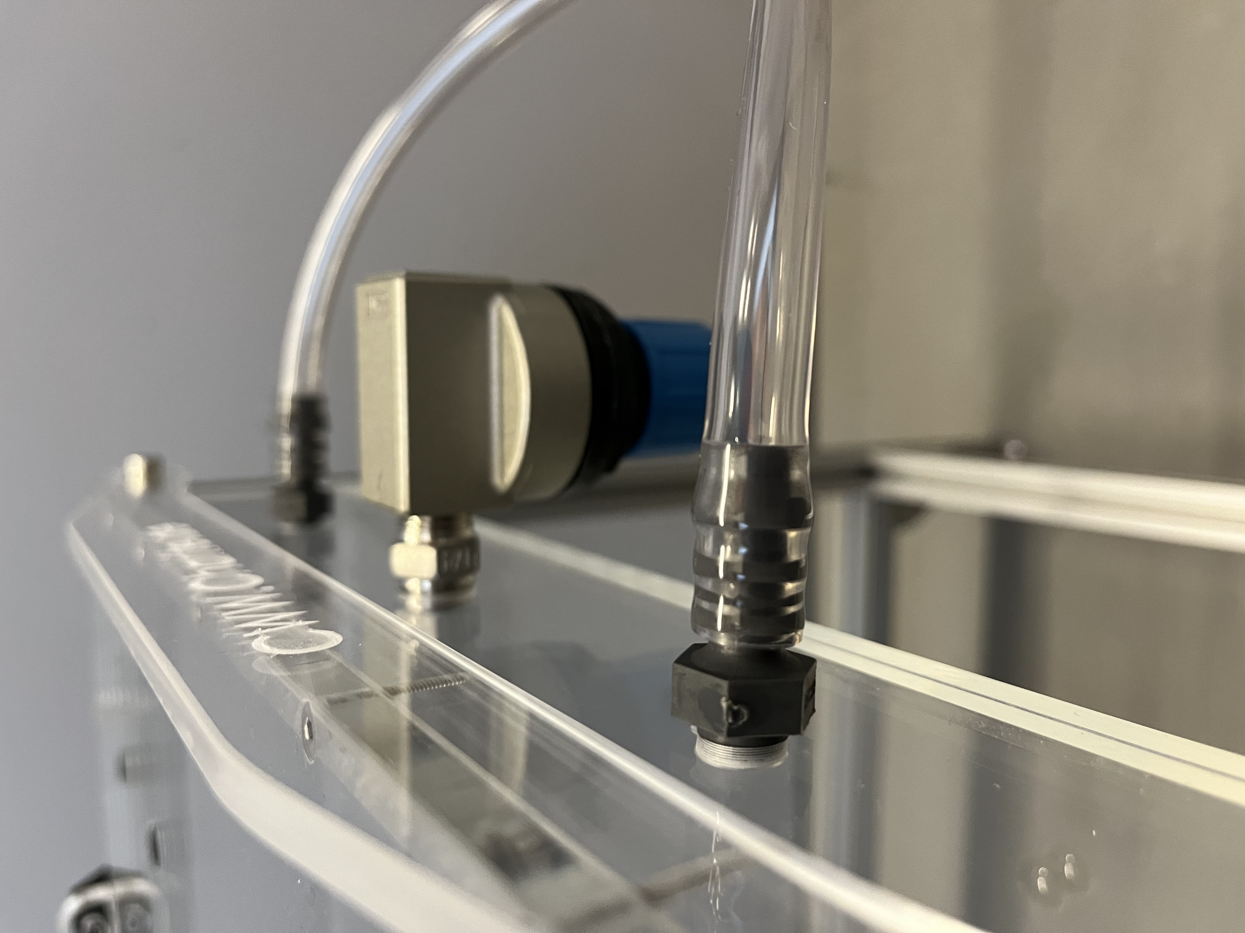
Picture of the pressure relief valve and incoming air pressure tubes

Step 1: Inserting of hose connection gland and pressure relief valve
These components take care of the incoming air and protection against overpressure.
-
Both following components will be placed at the short air table side with G 1/8" and G 1/4" thread predrills.
-
Insert the reducing fitting in the G 1/4" thread.
-
Place on the reducing fitting the pressure relief valve.
-
Place inside the G 1/8" threads the hose connection glands.
Step 2: Air hose
-
Combine two 200 mm compressed air hose with an Y-hose connector.
-
Append to the in one direction pointing end of the Y-hose connector another compressed air hose with the length of your need to the air pressure source.
-
Connect both 200 mm compressed air hose with the hose connection glands.
You have build the center air table now.