A Functional model explains what the product is made for. It is:
A description of the functions performed by a product.
An opportunity to break down a product into smaller pieces (modules) that can be more easily understood.
At the highest level of a functional breakdown (black box view), service functions are the effects (intended by its ecosystem actors) of the interaction of the product with its environment. (See actors analysis, Section 4.8).
At the intermediate and lowest levels of a functional breakdown (white box view), technical functions are input-output relationships transforming matter, energy or information flows. They are expressing in a non-solution neutral way and observable from inside the product. A set of technical functions is necessary for the realization of a service function (in contrast to solution neutral expression of the capabilities, Section 4.3).
Why should you define functional model?
A functional model helps to break down a complicated problem into simple sub-problems.
A functional model helps to anticipate failures occurring when an intended effect of the product is no longer produced on its environment.
A function is the main input to derive the functional requirements required to define the conditions of use of the product as well as to provide objective evidences through the validation and verification activities.
How to document a functional model?
The documentation of technical functions, which requires adopting an internal (white box) viewpoint on the product, consists in breaking down the service function into sub-functions. The decomposition process is no more solution neutral as it requires to make a decision at every indenture level. The functional decomposition requires two modelling approaches: function tree and functional graph.
See also Section 5.3 for the technical description of creating trees and graphs.
Functional tree
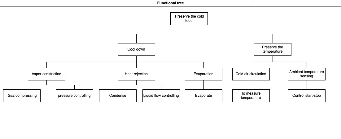
The functional tree is a top-down decomposition of function into sub-functions that helps to simplify the problem to solve.
The decomposition of technical functions creates a functional tree and, the technical functions are defined based on the functional requirements.
A top-down and bottom-up reading of the functional tree provides insight on the “how” and “why”, respectively.
The decomposition process should be stopped when the technical function is sufficiently detailed to reuse, make, or buy a design solution.
Example
Image of functional tree of XYZ cargo-ADD ONS
1. What minimum documentation should the functional tree provide?
- A model specifying the kinds of technical functions and their sub
-functions in the format of a tree.
How to implement the functional tree?
Use functional modeling language for representation, such as
UML (Use Case diagram)
SysML (Block Definition, Activity, or Internal Block diagram)
SADT/IDEF0
Functional flow block diagram
Use open-source software for modeling the tree representation, such as:
draw.io (diagram.net)
excalidraw
Papyrus
Modelio
Capella
Functional graph
The functional graph is a multi-level logical articulation of technical functions. - Relationships between functions are in/out-going flows of matter, energy, or information. - Logical AND/OR gates can be used to define concurrent or sequential functions. - Articulation of technical function can describe as input-output relationships transforming flows by using the functional modeling language in the format of the graph
Example
The image shows the functional graph of the relationship between technical functions for maintaining food quality by ADD-ONS of XYZ cargo.
See Section 5.3 for information about creating tree and graph
What minimum documentation should the functional graph provide?
A model specifying a multi-level logic of relationships between technical functions (refer to functional graph of XYZ Cargo-ADD ONS)
How to implement the functional tree?
Use functional modeling language for representation, such as
draw.io (diagram.net)
excalidraw
UML (Use Case diagram)
SysML (Block Definition, Activity, or Internal Block diagram)
SADT/IDEF0
Functional flow block diagram
Use open-source software for modeling the tree representation, such as
Papyrus
Modelio
Capella
The link below shows an example of functional block diagrams of an open-source project
The model will enable the makers to understand the analysis of the physical behavior of a product, this analysis supports the decision made at the later stages of design. This analysis is most often done using simulation software, or is made unconsciously in the designer head. Having some explicit model (even when no software is used) can be very useful to share ideas between designers.
The behavior model:
describe the behavior of a product when it receives a stimulus.
could be the mathematical description of the physical product, this description may be made via a modelling software (Simulation model) that should be included in the documentation.
is the physical interactions between the components of a design, as well as between the design and its environment. An artifact exhibits certain behaviors not only by the change or maintaining of its physical state, but also by several interactions that take place inside the artifact, as well as with its environment.
Why should you define behavioral model?
The behavioral model identifies the properties for understanding the calculation, simulation, and environment of the product.
The behavioral model could provide the simulation of any given physical phenomenon using numerical techniques.
Behavior model describes how the artifact implements its function and is managed by engineering principles and physical rules that are included in a behavioral model.
How to document a behavioral model?
Documentation should indicate the type of model, variables used to define the model, software used for the simulation, and results of the simulations.
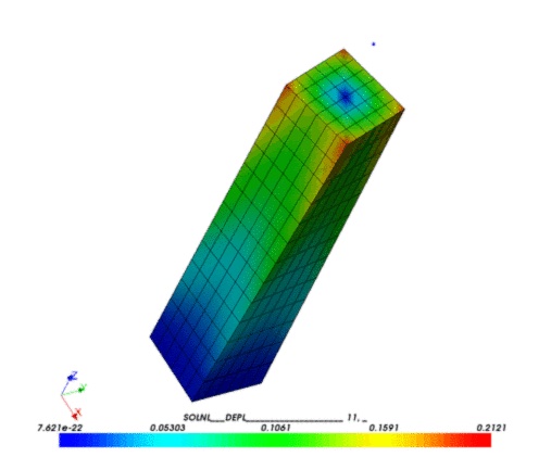
Examples
type of model:
mechanical simulation (finite element analysis (FEA) and computational fluid dynamics (CFD) are two types of mechanical simulation)
physical simulation
Thermo-mechanical simulation
Electronical simulations
variables used in the model:
Specification of the geometrical model (refer to editable file format in the structural model)
Material characteristics (refer to structural model)
Initial conditions such as initial stresses, temperatures, velocities.
Boundary conditions can be imposed on individual solution variables such as displacements or rotations.
Kinematic constraints that are several of the fundamental solution variables in the model (Linear constraint equations) or multi-point constraints (General multi-point constraints) can be defined.
Interactions that are contact and other interactions between parts can be defined.
This section will give an overview of the structural model, while details are given in the specific mechanical (also called architectural, Section 5.4), electrical (Section 5.6) and software (Section 5.5) architectures sections. Note that sometimes, these different models are presented together in a single graphics.
The Structural model explains the physical structure of the product and its components, it is:
A description of the components (the combination of parts) of a product and their relationships.
An opportunity to specify the geometric elements, dimensions, topology, and other physical properties of the product.
The potential solutions (concepts), which are the result of the conceptual design phase.
The set of mechanics theories that obey physical laws required to study and predict the behavior of structures.
Why should you define structural model?
A structural model helps to describe the geometric elements (design feature, dimensions, constraints, etc.), topology (assembly constraint between components, tolerances, components mating conditions, etc.), and characteristics of the product.
A structural model helps to decide the physical form of the product and its components to ensure that the structure is fit for its intended purpose.
Structural model provides users with a physical model of the product, components, and characteristics of the material at the design phase that enable the stakeholder to understand the geometry, material reaction to external factors, etc.
The structural model ensures that the structures are safe and fulfill the functions for which they were built.
How should you define structural model?
The first level of definition is often to show how things are related together in a tree or graph, using “modeling language” such as “SysML (Block Definition, Activity, or Internal Block diagram)” or “UML”.
The software architecture represents the repository details of all the software and firmware that is necessary for reusing and running the project. Indicate how the different software depend on each other.
It might be interesting to describe the data flow and its format.
See Section 5.3 for information about how to document this. Provide both an image and the editable files, as well as instruction how to use them.
Software and Firmware details
Please provide :
Clear installation guide
Description of programming algorithm
The source code
Version of software and its dependencies (both hardware and software dependencies)
Computer assisted design is usually used to create structures from the models. The designs should be best provided in their raw format (Native formats), an editable standard format (Neutral formats), and a exported format used for manufacture. For example, a fusion .f3d file, a Step file and a STL file.
CAD for electronics, PCB design
To reuse a electrical design, it should provide information consist of:
Model design should be provided in a format that can be used to manufacture each piece: usually STL and STEP file for 3D objects, and SVG file for 2D design, electrical design can be shared in the editable format directly. These formats are often easier to preview, and will help understand the structural/electrical design.
Note that the file is often not sufficient to reproduce one piece and manufacturing information must be given, as explained in Section 6.12.
Editable file format
An editable file format is a standard way that information is encoded for storage and allows the makers to study, modify the geometry of a model and reuse it.
To reuse a design model, it should provide information consist of:
The image shows the functional graph of the relationship between technical functions for maintaining food quality by ADD-ONS of XYZ cargo.
 GIF image of the model.
{width=400}