Product development -foreseen cost (money and time)
Product development - requirements
A requirement is a formal statement that specifies when condition C is true, property P of object O is actual and its value shall belong to domain D.
It is usually defined at the end of the ecosystem and user analysis.
The minimum set of independent requirements can completely characterize the needs of the product in the functional domain.
Functional requirements describe qualitatively the system functions or tasks to be performed in operation.
Requirement can state as follows: The [stakeholder] need [Property] [object] [Action verb] at [Condition]
Example of the functional requirement that ADD-ONS of XYZ cargo provides for the food producers, as a stakeholder, to preserve the quality of food.
In this example, we assumed a refrigerator on the ADD-ONS could help the food producers to cool down and preserve the temperature of food.
So, we defined some functional requirements (FR) based on this assumption that consist:
FR1: To maintain the quality of food, the food producer needs to main the material at cold temperature (between 3 °C and 10 °C) for short-term preservation (3h) or long-term preservation (24h).
FR2: ADD-ONS shall fix the internal ADD-ONS >temperature for 7 °C.
FR3: To create a cold ambient in the cooling down system, the ADD-ONS shall compress the low temperature and pressured gas to start the cooling cycle.
FR4: the cooling down system shall control the pressure of exit hot gas
FR5: the hot and pressured exit gas needs to meet the cooler external ambient temperature to become a liquid.
A constraint is a choice that makes certain designs “not allowed” or inappropriate for their intended use.
The constraint is a restriction, limit, or regulation imposed on a product.
There are two kinds of constraints: input constraints and system constraints.
Input constraints are imposed as part of the design specifications.
System constraints are constraints imposed by the system in which the design solution must function.
Example XYZ Cargo ADD-ONS, constraints for maker of ADD-ONS
User should be able to dismantle ADD-ONS with a maximum one wrench and one screwdriver
Users should be able to customize the modules of ADD-ONS to fit their use.
The ADD-ONS should enable the users to do the assembly of components in a short time (10 minutes) and the maker shall select the resistance material for using ADD-ONS in different weather conditions.
ADD-ONS should be dismantled for recycling purposes.
A service or capability is an effect intended by a actor/user resulting from the interaction of the product with its environment (i.e. what the product is for).
NB: this will relate to the user analysis section of the documentation that defines the actors and interactions.
Services can be stated as follows: The [Product] shall enable [the actor] to [Action verb] (for example The product shall enable end-user to clean its teeth)
Services provide users with an exchange value that can be included in an economic system.
Services are intended effects that can be observed from outside the product (“black box” external view).
Services are defined in a solution neutral-way.
Example of services for ADD-ONS of XYZ Cargo
The ADD-ONS shall enable the food producer to store food
1.1 solid (10 kilos)
1.2 liquid (5 litrs)
The ADD-ONS shall enable the food producer to heat food
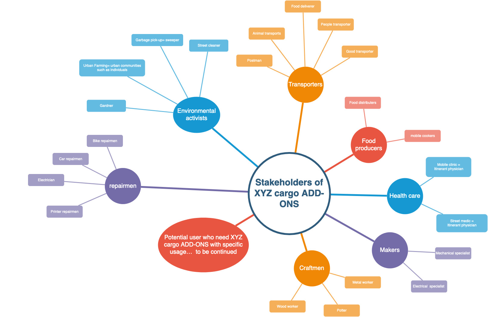
this is sometimes refered to a "stakeholder analysis", but we avoided that term in this template.
The ecosystem generally refer to all the actors (human and non-human) who (may) have an interest in a product. Among them, there are both internal players, such as users and participants of the project, and external players that are represented by the potential user of products or external entities.
It is not necessarily a person (for example: airports as an actor when designing a two-deck aircraft).
They can indirectly affect, be affected by the product (for example: neighborhood or biodiversity when designing an airport).
The ecosystem is often best represented via a graphics or a mindmap. This analysis may be necessary to make design choice that will fit the ecosystem inside which the hardware is supposed to work.
NB: The user target groups is one of these actors and should be determined with more accuracy, it is defined more extensively elsewhere.
User analysis - target groups (who will use the product)
Target group is a specific actor in hardware development, one should take much care in defining who they are and what they want.
User analysis - External interfaces (how will they use the product)
External interfaces are interactions between the product and the actors (including users).
An interface has a direction (in, out, or in-out)
An interface is made of a flow (matter, energy, or signal)
Example: XYZ Cargo ADD-ONS
Identify the interactions between food producer and the product, specify needs and uses: - out: mechanical countainment - out: warmer and cooler - out: thermal energy
A Functional model explains what the product is made for. It is:
A description of the functions performed by a product.
An opportunity to break down a product into smaller pieces (modules) that can be more easily understood.
At the highest level of a functional breakdown (black box view), service functions are the effects (intended by its ecosystem actors) of the interaction of the product with its environment. (See actors analysis, Section 4.7).
At the intermediate and lowest levels of a functional breakdown (white box view), technical functions are input-output relationships transforming matter, energy or information flows. They are expressing in a non-solution neutral way and observable from inside the product. A set of technical functions is necessary for the realization of a service function (in contrast to solution neutral expression of the capabilities, Section 4.4).
Why should you define functional model?
A functional model helps to break down a complicated problem into simple sub-problems.
A functional model helps to anticipate failures occurring when an intended effect of the product is no longer produced on its environment.
A function is the main input to derive the functional requirements required to define the conditions of use of the product as well as to provide objective evidences through the validation and verification activities.
How to document a functional model?
The documentation of technical functions, which requires adopting an internal (white box) viewpoint on the product, consists in breaking down the service function into sub-functions. The decomposition process is no more solution neutral as it requires to make a decision at every indenture level. The functional decomposition requires two modelling approaches: function tree and functional graph.
See also Chapter 5 for the technical description of creating trees and graphs.
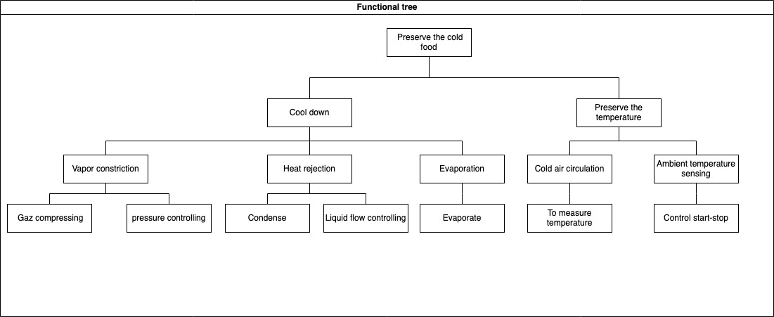
Functional tree
The functional tree is a top-down decomposition of function into sub-functions that helps to simplify the problem to solve.
The decomposition of technical functions creates a functional tree and, the technical functions are defined based on the functional requirements.
A top-down and bottom-up reading of the functional tree provides insight on the “how” and “why”, respectively.
The decomposition process should be stopped when the technical function is sufficiently detailed to reuse, make, or buy a design solution.
Example
Image of functional tree of XYZ cargo-ADD ONS
1. What minimum documentation should the functional tree provide?
- A model specifying the kinds of technical functions and their sub
-functions in the format of a tree.
How to implement the functional tree?
Use functional modeling language for representation, such as
UML (Use Case diagram)
SysML (Block Definition, Activity, or Internal Block diagram)
SADT/IDEF0
Functional flow block diagram
Use open-source software for modeling the tree representation, such as:
draw.io (diagram.net)
excalidraw
Papyrus
Modelio
Capella
Functional graph
The functional graph is a multi-level logical articulation of technical functions. - Relationships between functions are in/out-going flows of matter, energy, or information. - Logical AND/OR gates can be used to define concurrent or sequential functions. - Articulation of technical function can describe as input-output relationships transforming flows by using the functional modeling language in the format of the graph
Example
The image shows the functional graph of the relationship between technical functions for maintaining food quality by ADD-ONS of XYZ cargo.
See Chapter 5 for information about creating tree and graph
What minimum documentation should the functional graph provide?
A model specifying a multi-level logic of relationships between technical functions (refer to functional graph of XYZ Cargo-ADD ONS)
How to implement the functional tree?
Use functional modeling language for representation, such as
draw.io (diagram.net)
excalidraw
UML (Use Case diagram)
SysML (Block Definition, Activity, or Internal Block diagram)
SADT/IDEF0
Functional flow block diagram
Use open-source software for modeling the tree representation, such as
Papyrus
Modelio
Capella
The link below shows an example of functional block diagrams of an open-source project
The model will enable the makers to understand the analysis of the physical behavior of a product, this analysis supports the decision made at the later stages of design. This analysis is most often done using simulation software, or is made unconsciously in the designer head. Having some explicit model (even when no software is used) can be very useful to share ideas between designers.
The behavior model:
describe the behavior of a product when it receives a stimulus.
could be the mathematical description of the physical product, this description may be made via a modelling software (Simulation model) that should be included in the documentation.
is the physical interactions between the components of a design, as well as between the design and its environment. An artifact exhibits certain behaviors not only by the change or maintaining of its physical state, but also by several interactions that take place inside the artifact, as well as with its environment.
Why should you define behavioral model?
The behavioral model identifies the properties for understanding the calculation, simulation, and environment of the product.
The behavioral model could provide the simulation of any given physical phenomenon using numerical techniques.
Behavior model describes how the artifact implements its function and is managed by engineering principles and physical rules that are included in a behavioral model.
How to document a behavioral model?
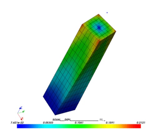
Documentation should indicate the type of model, variables used to define the model, software used for the simulation, and results of the simulations.
Examples
type of model:
mechanical simulation (finite element analysis (FEA) and computational fluid dynamics (CFD) are two types of mechanical simulation)
physical simulation
Thermo-mechanical simulation
Electronical simulations
variables used in the model:
Specification of the geometrical model (refer to editable file format in the structural model)
Material characteristics (refer to structural model)
Initial conditions such as initial stresses, temperatures, velocities.
Boundary conditions can be imposed on individual solution variables such as displacements or rotations.
Kinematic constraints that are several of the fundamental solution variables in the model (Linear constraint equations) or multi-point constraints (General multi-point constraints) can be defined.
Interactions that are contact and other interactions between parts can be defined.
It is advisable to look for similar project one can join, instead of starting a new one.
It is reasonable to invest quite a lot of time in looking for similar projects. OSH are often difficult to find and comprehend, but finding projects may save you a lot of time and hassle. Indeed, you may learn a lot about your needs, refine your ideas, and may even find collaborators while browsing existing OSH projects.
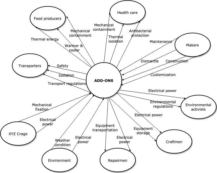
The image shows the functional graph of the relationship between technical functions for maintaining food quality by ADD-ONS of XYZ cargo.
 GIF image of the model.